User Manual
Index
Introduction
Safety
Thank you for buying [[]]! We at SYNTHFOX want people to have as much fun with and make as much good use out of our gear as possible. But first and foremost, we want our users and their synthesizer systems to be safe. This device is not a consumer grade piece of electronics. This is a specific part (module) that is to be installed into a Eurorack system and interfaced with its other parts. The user handles the installation process - extra care should be taken. Please, read this notice carefully!
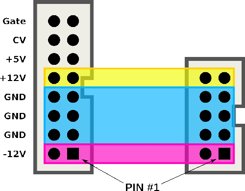
[[]] has a keyed connector. The included ribbon cable is tested to comply with standard Eurorack boards, and it cannot be inserted the wrong way into the module without excessive force. However, the power distribution boards may vary, and it is up to the user to understand which way to connect the ribbon to the distribution boards. The red line on the ribbon cable marks the -12 volts line. The module should be connected like in the picture below: on the left side is the bus board connector, and on the right side is the connector on [[]].
Installation procedure guide
- Find a suitable place for the module in your system. [[0]] is [[1]] HP wide. You can use ModularGrid for planning in digital.
- Disconnect the power supply / power cord from your modular system. Do not just turn off the switch: pull the wire.
- Install the ribbon cable into the power distribution board: the wider, 16-pin end goes into the board.
- If you have keyed connectors on your board, the ribbon will comply with the key: make sure it requires no excessive force to insert, only a little.
- If you have a board with bare pins, make sure to locate your -12V power supplying rail. It is usually marked on the board as "-12", "NEG", "-", "RED" or such. The red stripe on the ribbon has to face the -12V rail!
- Connect the ribbon cable's smaller, 10-pin end into the module. All SYNTHFOX modules come with keyed power headers: make sure the ribbon is positioned so that the header keys connect. Additionally, the module's silkscreen has a line with a word "RED" next to it indicating the -12V side, which the red stripe on the power ribbon should align with.
- Bolt the module down to the rail fixings / sliding nuts using a screwdriver. M3 plus-head screws are included in necessary quantity, but one may opt to use their own for cosmetic reasons: the advised length is 6mm.
- Plug the cord back in and turn the system on. Everything should turn on without any power delays or such. If so: happy patching!
- If anything seems out of order, turn off the system immediately and check the installation; don't forget to unplug the power cord. If the installation is correct, uninstall the module and reach out for help.

Controls
Flowchart
Full Overview
[[]]Patch Ideas
Jumpers & Calibration
Information may differ from revision to revision: please, check the back of your module if you're unsure about yours. The revision is usually written next to the backside stylized module logo.
Warranty
Any new SYNTHFOX module is protected by a 2 year warranty. In the unlikely case of a malfunctioning unit, a proof of first-hand purchase is all that is necessary to get the unit fixed or swapped free of charge. Units bought off-hands and units that received bus board pin header reversal damarge are warranty exempted, but we can still look into it on a case-by-case basis.