DELTA T USER MANUAL

DELTA T USER MANUAL

|
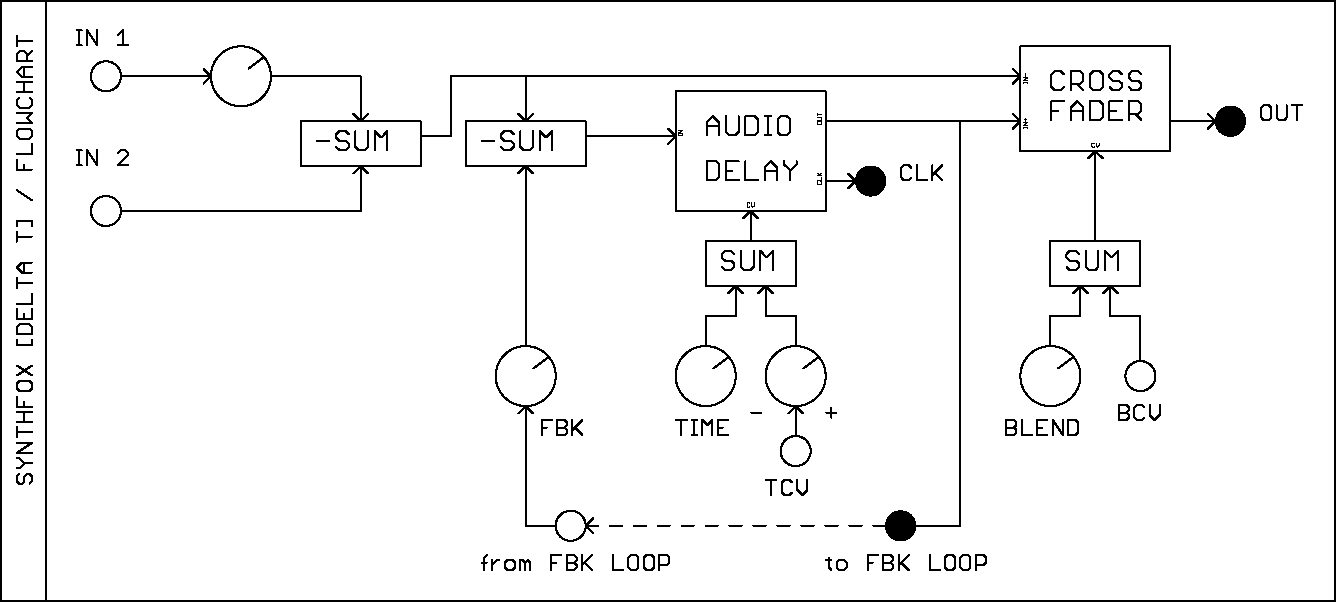
Thank you for buying DELTA T by SYNTHFOX. DELTA T is an audio delay module featuring voltage control over time, a timing pulse output, an open feedback loop and much more. In this manual, an overview of DELTA T's features is given, as well as some additional information, such as a flowchart (logic diagram) of the module's insides and some patch ideas. Please, read the safety notice carefully! |
Thank you for buying DELTA T! We at SYNTHFOX want people to have fun with and make as much good use out of our gear as possible. But firstly, we want users to be safe and their synthesizer systems to be fully functional. This device is not a consumer piece of electronics. This is a specific part (module) that is to be installed into your Eurorack system and interfaced with its other parts. The user handles the installation process - extra care should be taken!
DELTA T has a keyed power connector. The included ribbon cable is tested to comply with standard Eurorack boards, and it cannot be inserted the wrong way into the module. However, the power distribution boards may vary, and it is up to the user to understand which way to connect the ribbon to the distribution boards. The red line on the ribbon cable marks the -12 volts line. The module should be connected like in the picture below: on the left side is the bus board connector, and on the right side is the connector on DELTA T.

image by David Haillant
When installing the module:
The module should now be ready to play. Have you any troubles, feel free to reach out to SYNTHFOX through synthfoxmodular@gmail.com.

Meet DELTA T, an audio delay unit that goes beyond usual audio delay functionality. DELTA T is based around the PT2399 delay chip, which serves as a basis for many guitar delay pedals and delay-centered modules. The SYNTHFOX take on this chip aims to use as much of its capabilities as possible, while retaining the trademark lush plus janky sound of the PT2399.
DELTA T features two signal inputs IN1 and IN2. These inputs are AC-coupled, meaning that a slowly changing or constant signal, like a triangle LFO or a DC offset, will get blocked off by the input circuit. First input has a volume control knob, whereas the second input is passed as is.
The OUT signal output of DELTA T is an AC-coupled mixture of the inverted sum of the input signals and the delayed sound from the delay circuit. It is located at the bottom right of the module. The mixture proportion is controlled by a vactrol crossfader, and is set with the BLEND knob and the unattenuated BCV (blend conrol voltage) input. By default, this crossfader fades between 100% dry signal (only input mix) and 100% wet signal (only delay circuit's output), but a jumper on the back can change this behavior so that the mix always has a set volume for dry, while blending in the wet.
DELTA T's TIME setting is set with the big white knob at the top of the module and the TCV (time control voltage) input. TCV has a dedicated attenuverter knob below the initial time control. It allows for either adding or subtracting the TCV input to/from the initial TIME setting. Time range of the delay is a few hundred milliseconds (distinct echo) to a few milliseconds (metallic bucket buzz).
The FBK knob sets the amount of feedback. The more this knob is turned clockwise, the more delay repeats will occur, up to self-oscillation. The feedback of the circuit is inverted, so it is tamer/smoother than in most PT2399-based units. The feedback loop is broken out to the two jacks in the FBK.LOOP box, connected to the FBK knob with a dash-dot line. By default, audio from the feedback loop output (left jack) is normaled to the feedback loop input (right jack): this lets the signal circulate around the delay chip unaltered. Inserting a voltage controlled amplifier into the loop (loop out -> vca in, vca out -> loop in) will break the normalled connection and provide voltage control over feedback amount. Likewise, a bandpass filter in this loop will allow dynamic control of the delay tone.
Last, but not least, there is the CLK output located to the left of the OUT. CLK outputs a pulse that's synchronised to the current actual delay time of the unit, and is indicated with the only LED on the module located to the left of the TIME control. This pulse is bipolar and hot, meaning it is a bit less than 12v when the LED is lit, and a bit more than -12v when the LED is off. It can be used as a tempo clock, bipolar LFO, or even as a sound signal - but in this case, it has to be attenuated to at least 50%, because initially it is very loud.
|
Ⓐ Initial time setting control
Ⓑ Time CV (TCV) input
Ⓒ TCV attenuverter
Ⓓ Time tempo indicator LED
Ⓔ Audio input 1
Ⓕ Audio input 1 volume control
Ⓖ Audio 2 input (no volume control)
|
Ⓗ Feedback amount control
Ⓘ Feedback loop send (normaled to fbk. loop return)
Ⓙ Feedback loop return
Ⓚ Blend (dry/wet) control
Ⓛ Blend CV (BCV) input
Ⓜ Tempo clock output
Ⓝ Audio output
|
This version of DELTA T has one trim potentiometer and no jumpers. The trimpot is calibrated for optimal settings at production and don't have to be calibrated. The trimpot sets the maximum range to which TCV can affect the delay time. The actual delay time difference at higher time settings might be negligible, so this trimmer is set for optimal time ranges across the entire big time setting knob.
This version of DELTA T has two trim potentiometers and one jumper. The trimpots are calibrated for optimal settings at production and don't have to be calibrated. Both of them set the time range of the module. MIN.TIME sets the minimal delay time of the module, and if set too low, the audio output will be very noisy a low TIME settings, or even not sounding at all. One may want to use this for artistic purposes, though. The TIME RANGE trimpot sets the maximum range to which TCV can affect the delay time. The actual delay time difference at higher time settings might be negligible, so this trimmer is set for optimal time ranges across the entire big time setting knob. The BLEND MODE jumper selects between the two blending modes, and the default position for it is XFADE. In XFADE mode, the BLEND control will fade between dry-only (mix of IN1 and IN2) to wet-only (the output of the delay chip). In MIX-IN mode, the delay sound will be gradually added to the dry signal, but the dry signal itself will remain at a more or less constant volume.
Although you can use DELTA T as a conventional sound delay unit, its capabilities extend far beyond a simple delay. Here are some ideas that can get you started with creative DELTA T patching!
This patch will require a VCF and explores a basic feedback loop augmentation technique. Set the TIME knob to about 9 o'clock, FBK to noon, BLEND to 11 o'clock. Patch the FBK.LOOP output to the VCF input, and the VCF output to the FBK.LOOP input. Feed a sound (preferably a sharp percussive one) to IN 1, and monitor the module's sound output. You can now control the tone of the delayed signal dynamically with the VCF's cutoff and resonance. Moreover, it is now possible to dynamically control the feedback tone/character with control voltages, in addition to the built-in time and blend ratio voltage control.
People would base the timing of krell (generative) ambient patches off a cycling function generator, an LFO or a clock source. But why not to base it on DELTA T? For this patch, you will need:
Connect noise to the signal input on the S&H or grab your ready-made stepped random source. Connect the DELTA T's CLK output to a signal multiple (or use a passive splitter wire/stackable patch cable). Use one of the mult outputs to trigger the stepped random. Put the random voltage output to DELTA T's TCV input. Set the big TIME knob to about 9 o'clock, adjust the TCV attenuverter to taste, feedback to about 1 o'clock, blend to 10 o'clock. Mult another copy of the CLK output to your percussive sound, and connect its sound output to the DELTA T audio input. You will get a very non-typical unsynchronized synchronization effect: the delay taps will happen exactly in sync with the percussive sound, however, each tap will be of a random length. Because of the long feedback tail, the previous taps will get pitch-warped and will generate pitch-shifted copies of the original sound around it.
We all know and love slamming the feedback on a PT2399 delay full clockwise without any input and listening to the hiss that it makes. Take this up a notch using the built-in crossfader! Set the initial TIME control to 9 o'clock, IN1 fully CCW, FBK almost fully CW and BLEND fully CW. Listen to the sound output: you should be getting a hissy, ringing, overdriven texture. Play with the FBK and TIME until happy. Now, bring the BLEND knob fully CCW, grab the CLK output and patch it to the BCV input. You will get a pulsating version of the texture, and the pulse period will be set by the delay TIME. Of course, you can grab any other envelope and cotnrol the texture volume externally using the BCV input. We recommend trying a short, plucky envelope first for some percussive sounds.
v1.0: initial module release
v1.1: updated colour scheme, removed initial time trim, fixed 1.0 mistakes
[20211211] 1.0.0: initial document
[20211214] 1.0.1: minor fixes, suggested by Justin Sullivan and trev - thank you!
[20220430] 1.0.2: new pictures, module version 1.1 related updates
Happy patching!